Ansul I-101 Industrial Fire Suppression Systems
Features
- UL Listed
- Complies with UL 1254 Standard
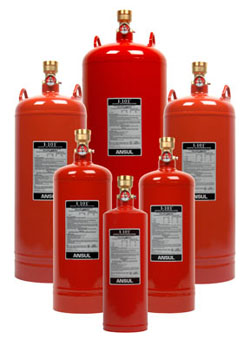
- 15 lb (6.8 kg), 17 lb (7.7 kg), 25 lb (11.3 kg), 35 lb (15.9 kg), 50 lb (22.7), and 70 lb (31.8 kg) size tanks available with ABC dry chemical for total flooding applications
- 25 lb (11.3 kg) and 50 lb (22.7 kg) size tanks available with BC dry chemical for local application overhead and local application tankside
- Several Basic Application Methods:
– Total Flooding: Overhead or sidewall
– Local Application: Tankside or overhead - Mechanical or Electrical Detection
- Low Temperature Total Flooding Application –20 °F (–29 °C)
Application
The ANSUL® I- 101™ Fire Suppression System is an automatic system using ABC dry chemical agent for Class A, B and C fires, and BC dry chemical agent for Class B and C fires, stored under pressure using dry nitrogen gas at 450 psi (31.0 bar) at 70 °F (21 °C). The system is designed to protect a wide variety of hazards involving flammable liquids and gases, wood and paper, and energized electrical equipment. The system can be used on most hazards found in industrial settings. Some examples include:
- Vehicle Paint Spray Booths
- Open Face Paint Spray Booths
- Prep Stations
- Hazardous Storage Buildings
- Dip Tanks
- Paint Lockers
- Flammable Liquid Storage Facilities
- Stock Rooms
- Printing Machines
- Mixing Tanks
- Electrical Motors
- Pumps
- Switchgear Rooms
- Indoor Transformers
- Wood Finishing Operations
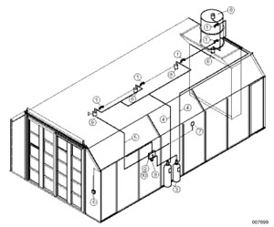
- Fusible link detector
- MCH3 control head
- I- 101 agent tank(s)
- Agent piping
- Detection conduit
- Manual pull station
- Alarm bell
- Discharge nozzle(s)
- Pneumatic time delay (vehicle paint spray booth only)
- MB-P2 control head bracket
Description
The ANSUL I- 101 fire suppression system is designed for protection of vehicle paint spray booths, open face paint spray booths, hazardous storage buildings, and many other industrial hazards. The dry chemical extinguishing agents are appropriate for Class A, B and C fires (ABC dry chemical) as well as Class B and C fires (BC dry chemical). A careful hazard survey should be conducted to properly define the type of fire to be suppressed. For hazardous material storage applications, materials and their classifications must be considered when choosing appropriate application methods. For paint spray booth applications, the predominant hazardous material is typically the material being applied to the vehicle/component that is being painted. The object to be coated should also be considered. The ANSUL I- 101 system utilizes a protection concept as defined by
NFPA Standard No. 17 – “Dry Chemical Extinguishing Systems,” NFPA Standard No. 33 – “Spray Application Using Flammable and Combustible Materials,” NFPA 30 – “Flammable and Combustible Liquids Code,” and NFPA 72 – “National Fire Alarm Code.” Underwriters Laboratories provides pre-engineered system application parameters allowing the flexibility to protect a variety of hazardous material storage building layouts, paint spray booth applications.
Specifications
Suggested Architect’s Specifications
1. General
1.1 – The fire extinguishing system shall be the stored pressure, dry chemical, pre-engineered, fixed nozzle type manufactured by ANSUL. The system shall provide for the protection of the hazardous material storage building(s), paint spray operations, and/or other appropriate applications described in drawing _______________. (Note drawing number and revision.)
1.2 – The system shall be capable of automatic and manual actuation. It shall be UL Listed and installed in conformance with National Fire Protection Association Standard No. 17 – “Dry Chemical Extinguishing Systems,” No. 30 – “Flammable and Combustible Liquids Code,” NFPA
33 – “Spray Application Using Flammable and Combustible Materials,” and NFPA 72 – “National Fire Alarm Code,” and comply with all local and/or state Codes and Standards.1.3 – The system shall be designed for operation at ambient temperatures
from –20 °F to 120 °F (–29 °C to 49 °C).
2. Tank and Agent
2.1 – Agent. The system shall use ANSUL monoammonium phosphatebased or sodium bicarbonate-based dry chemical agent.
2.2 – Tanks. Steel tanks manufactured, tested, and marked in accordance with DOT 4B 350 or DOT 4B 500 shall be used to store the extinguishing agent. A-15ABC tanks shall be used with extinguishing agent fill weight of 12.5 lb (5.7 kg). A-17ABC tanks shall be used with extinguishing
agent fill weight of 17 lb (7.7 kg). A-25ABC/BC tanks shall be used with extinguishing agent fill weight of 25 lb (11.3 kg). A-3 5 A B C tanks shall be used with extinguishing agent fill weight of 35 lb (15.9 kg). A-50ABC/BC tanks shall be used with extinguishing agent fill weight of 50 lb (22.7 kg). A-70ABC tanks shall be used with extinguishing agent fill weight of 70 lb (31.7). All models are charged with dry nitrogen to 350 psi at 70 °F (24.1 bar at 21.1 °C).2.3 – Tank valve. A pressure sealed poppet-type valve having a brass body, stainless steel stem with rubber seat washer, fusible safety relief assembly, and pressure gauge shall be used on all agent tanks.
2.4 – Tank bracketing. Tanks shall be mounted vertically. The tanks shall be secured by use of a steel mounting bracket affixed to a rigid object capable of supporting the weight of the filled tank and the concussion of tank discharge.
3. Actuation Controls
3.1 – Control Head. The ANSUL I- 101 Industrial Fire Suppression System shall include a mechanical or electrical control head listed and approved to be used with the I- 101 system. The control head(s) shall be one of the MCH or ECH-Series Control Heads. The control head shall be mounted directly on the valve of the agent tank (for single-tank systems), in a MB-P2 control head mounting bracket (for actuating up to five centrally located agent tanks) or directly on the valve of a pneumatically (booster) actuated tank. An ANSUL-supplied 16 gram (0.56 oz) carbon dioxide pilot cartridge that complies with MIL-C0601G shall be used as an integral component of the control head. Control head status shall be visually indicated by a SET/FIRED indicator. 007710
3.2 – Time Delay (vehicle paint spray booth). The system shall have a T-10 Time Delay to allow for fan shutdown before agent discharge.
3.3 – Detection. The ambient temperature of the hazard area shall be monitored by fixed temperature mechanical or electrical thermal detectors. When the temperature of the hazard area exceeds the rating of any detector, the detector shall: a) release tension in a cable connected to
the control head, causing control head activation (when using mechanical fusible link detection), or b) close a normally open switch element within the detector, sending a signal to an ANSUL-approved releasing control unit which then energizes a solenoid in the control head, exercising
the control head when using electric thermal detection. In some applications, detection can be used with a circuit monitor and a UL Listed 24 VDC or 120 VAC secondary power supply.3.4 – Pneumatic actuation. For systems requiring more than five agent tanks, the system shall include a PAC pneumatic actuating tank acting as a booster actuator, whose valve opens upon activation of the control head. The valve shall release nitrogen from the PAC tank into the pneumatic
pipe and tubing network. This nitrogen shall depress a piston above the valve stem in each agent tank, opening each agent tank valve and releasing the pressurized agent.3.5 – Manual actuation. The system shall have mechanical manual actuation capability requiring no electrical power. This is accomplished locally by twisting the handle on the cover of the MCH or ECH Control Head, or remotely by means of an RPS-M remote mechanical pull station. When an ANSUL-supplied 24 VDC electric control unit is utilized with electric detection, an electric manual pull station can be used when it is properly connected to the ANSUL 24 VDC electric control unit.
3.6 – Auxiliary output. The system shall provide for the power shut-off of equipment within the hazard and to ventilation systems in the event of system actuation. This is accomplished by means of dry contacts on an MS- SPDT or MS-DPDT miniature switch installed in the control head. The miniature switch may also be used for auxiliary functions such as audible alarms. When the system is required to be connected to a fire alarm panel, in accordance with NFPA 72 – “National Fire Alarm Code,” the alarm initiating switch shall be used.
3.7 – Supervision. A Solenoid Monitor shall be used to supervise the integrity of all electrical actuation circuits, whether automatic or manual.
3.8 – Protection. A weatherproof enclosure designed and installed in accordance with NFPA 17 shall be used to protect the control head and agent tank when mounted in an exterior location.
4. Distribution Nozzles
4.1 – Nozzles. The system shall utilize ANSUL discharge nozzles to distribute agent throughout the hazard area. The type, quantity, location, and orientation of nozzles shall be in accordance with the ANSUL I- 101 Industrial Fire Suppression System Technical Manual, Part No. 435239 (General Purpose), Part No. 435237 (Vehicle Paint Spray Booth), or Part No. 435238 (Open Face Paint Spray Booth).
4.2 – Nozzle Caps. All nozzles shall be installed with nozzle caps to prevent foreign matter from entering the orifice of the discharge nozzle(s).
5. Pipe and Fittings
5.1 – Pipe. All pipe shall be Schedule 40 black iron, galvanized, chrome plated or stainless steel pipe in accordance with NFPA 17. All pipe ends shall be thoroughly reamed after cutting, and all oil, chips, and debris shall be completely removed prior to nozzle installation.
5.2 – Fittings. Standard weight (150 lb (68 kg) minimum) malleable, galvanized, chrome plated or stainless steel fittings shall be used.
5.3 – Size. All system pipe and fittings shall be sized and configured in accordance with the ANSUL I- 101 Industrial Fire Suppression System Technical Manual, Part No. 435239 (General Purpose), Part No. 435237 ( Vehicle Paint Spray Booth), or Part No. 435238 (Open Face Paint
Spray Booth). No substitutions are allowed.5.4 – Joints. No joint sealant shall be used in the discharge piping. Exception: TEFLON tape may be used.
5.5 – Straps. All system discharge pipe shall be securely fastened by means of UL Listed pipe hangers and/or pipe straps.
5.6 – Union. A union shall be installed in the discharge piping conveniently close to the tank valve to permit disconnection for inspection and service.